KiCad - The glue that makes KiCad stick
Long ago in the primeval times sea animals made the transfer from water to land. Ever since these needed legs to stand on and so does KiCad1. The legs of KiCad consist of three applications, which together make KiCad, KiCad (project manager), Eeschema (schematic editor) and Pcbnew (PCB designer). These applications are standalone, the sole dependency between them is communication.
Let’s explore some of the main advantages of this approach. To commence each of the applications can be easily maintained, updated and deployed. Furthermore the applications are also more easily scaled, since it is possible to only scale the application that needs scaling.
Additionally it is well known that solving multiple small problems is more simple as it is to solve one large problem. Considering KiCad is a very colossal and comprehensive application, it is more manageable to develop the program when its complexity is subdivided.
While all of this sounds very attractive, some of the main disadvantages of splitting the program into multiple applications is that it is more difficult to build a program in this way. Since these applications need to be able to communicate with each other and be backwards compatible. To expand on this, an user is very likely to pass through multiple applications, when working with KiCad, which increases the number of possible failure points. Whenever something goes wrong it is harder to pinpoint from which application the error originates from.
In the ensuing section on these components more will be elaborated, for a lot of the sections we used the source code of KiCad to find the information. But let us commence on a context overview of KiCad’s system.
The three main parties that are involved with the development and use of KiCad are shown in the next figure.
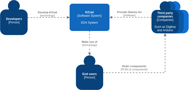
Figure: System Context
KiCad’s Components
It is time to take a look at what’s under the hood of this widely used PCB design program. The only thing needed to use KiCad is a desktop or laptop setup, which may be without ethernet connection, and of course, the KiCad software. The first thing to notice is that the software consists of three main execution environments; KiCad manager, Eeschema and Pcbnew, as depicted by the figure below. These can be categorized as so-called containers, which can function independently since they are separate desktop applications.
You could very well assume they are coupled very tightly and share a great deal of components. Anyhow you would be partly correct: they indeed share a lot of components between Eeschema and Pcbnew, nonetheless they are not coupled that tightly.
This section will explain and show the main components that are important or interesting in the code of the KiCad suite and show the connectors between those.
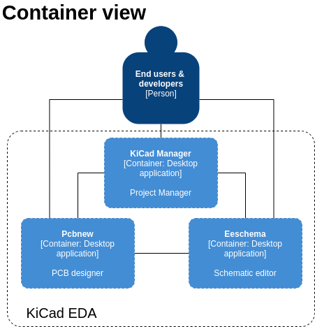
Figure: Container view.
Main components
Let us commence with the KiCad project manager. This will show the user the files and when a schema or pcb is clicked, the project manager starts the respective application just by running the command (e.g. pcbnew.exe) with the filename to open it. That is all of the communication between the project manager and the schematic/pcb designers. The designers do not even get a message when changing a filename. Other components of the KiCad project manager will not be discussed, because they are not that important or interesting.
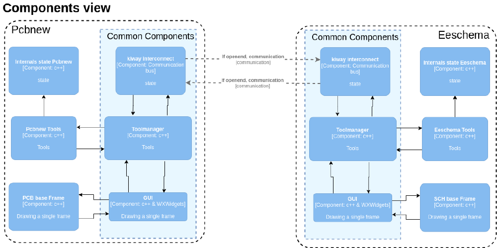
Figure: Components view.
On the contrary the applications Eeschema and Pcbnew do communicate with each other.
They communicate using WxEvents in the Kiway interconnect component. The communication is asynchronous, because it is between two different processes and very scarce in number. Messages are only sent when one application needs information from the other application, for example when the user clicks on the “Update PCB from schematic”, then a request message is sent to Eeschema to send the current schematic and Eeschema replies to Pcbnew. There is almost no communication by design, this way the applications can operate in a standalone fashion. Both of the applications run as a single process with a single thread, except for some special features like 3D rendering or footprint loading. This single thread approach requires the developers to make sure that the code does not take too long doing things, otherwise the GUI will become unresponsive.
There are a few common components, like the Toolmanager, the interconnect (as discussed previously) and the GUI rendering. The Toolmanager handles the onclick events and starts the correct tools (e.g. zoom, move, …) and indicates the rendering component (GUI) to re-render when needed. A few different parts will be discussed in the next sections.
The GUI parts are mostly identical, the WxWidgets2 rendering and board/schematic rendering are the same. There are some differences between the two, for example, which tools to show and two (slightly different) implementations of the RTree used. The internal format for the components is using an R-Tree, this is a way to build a spatial tree to enable faster rendering. This way the renderer has to only render the visible parts in the window and not those outside the frame.
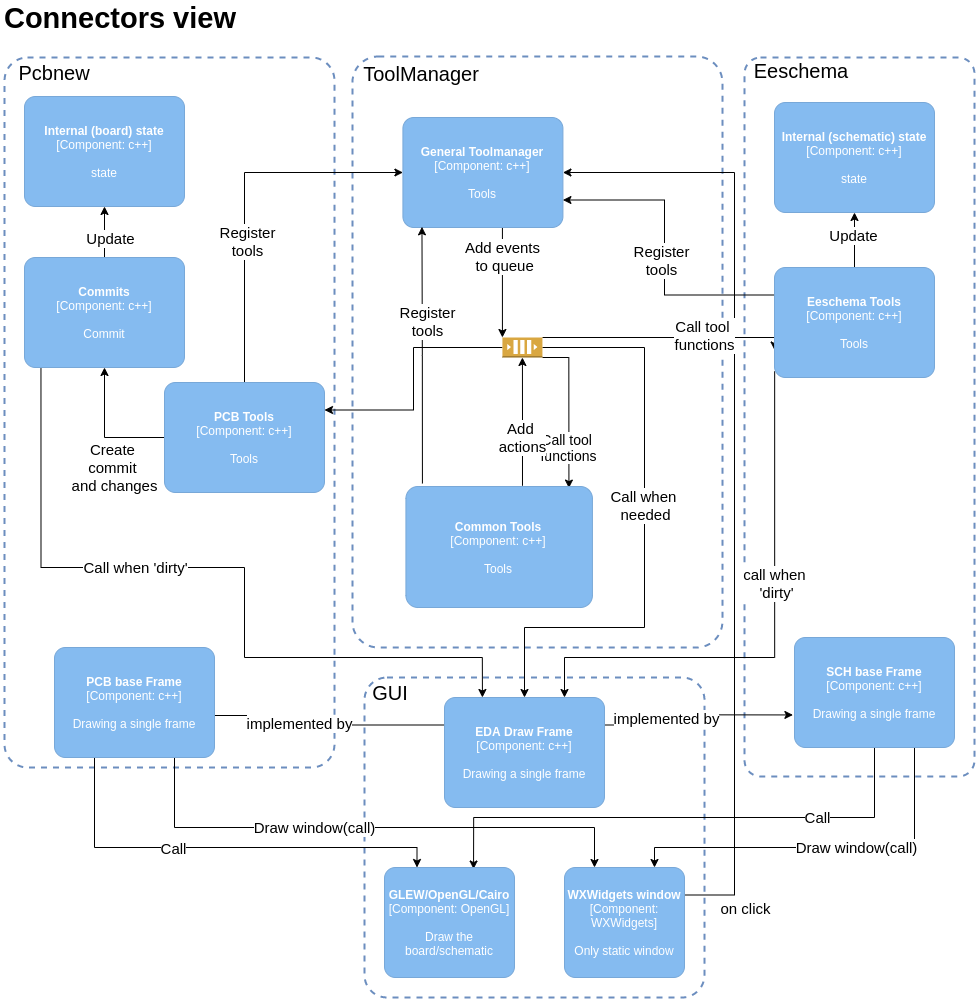
Figure: Connectors view.
Toolmanager
The Toolmanager receives onclick events from the GUI and looks through the registered tools to run the correct tool for that action. These events are put into a queue, probably to make the GUI more responsive. These events are then handled and range from refreshing the GUI to calling a tool function. There are some tools that are common, like zooming and moving components. Moreover there are also tools specific for a single application, like add symbol or route track. The PCB application has a special extra component, the “Commits” component. A commit can be created, components can be added/moved/deleted and then a commit is pushed. Only when a commit is pushed the GUI and internal state are updated and the history is modified. All of these invocations are just calls to the functions, besides the event queue no other queues are used and everything is synchronous.
Dialogs
Another interesting part of the architecture of KiCad is how the dialogs work. Usually dialogs are started in a new thread or a thread different from the processing thread (GUI thread + processing thread). KiCad has only one thread for both of these functions and the dialogs are also run from the same thread. This means that the UI is unresponsive for the duration of the dialog, however, this makes the communication a lot easier: no (extra) memory management is needed and it is synchronous.
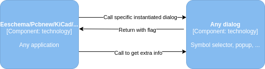
Figure: Dialog components.
Run time view
The previous figures only demonstrate the static interaction between different components inside the software. They do not explain the dynamic behaviour of the program, thus it does not illustrate the order of events. The sequence of events is very important and clarifies how the software should work. Though, it is not feasible to do this for every possible scenario. Therefore, we will only address two common and most interesting scenarios.
The first scenario describes the sequence of events when using tools within Pcbnew. Click events are captured by the WXWidgets components whereafter a call is made to the general Toolmanager which determines the specific tool that needs to be activated and adds it to the queue. In this scenario the tool is located in the PcbTools component. A single tool can activate multiple other tools, this is done by adding more events to the queue. Finally the PcbTool creates a commit which then updates the internal PCB state and then calls the GUI to update the frame.
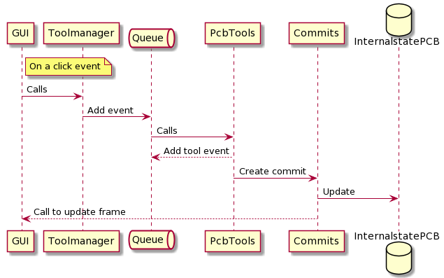
Figure: Run time view of tool activation in Pcbnew.
The second scenario illustrates the use of the Kiway interconnect between the Eeschema and Pcbnew application. Whenever a schematic is designed in Eeschema the “Update PCB from schematic” tool can be used to generate, or merely to update, the netlist towards the Pcbnew application. The sequence, which is illustrated below, starts after the Toolmanager receives the click call from the GUI interface, as illustrated by the previous run time view.
The tool manager of Eeschema will activate the appropriate tool function, this tool function will first check, via Kiway, whether Pcbnew is already active. Whenever this is not the case it will be activated via Kiway. Thereafter a “mail” will be sent via the interconnect and the control will be given back to Eeschema. Pcbnew receives the mail and activates the corresponding tasks via its own tool manager. It is important to note that this communication via the Kiway interconnect is asynchronous.
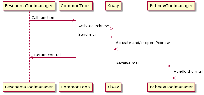
Figure: Run time view of “Update PCB from schematic” tool from Eeschema.
Development View
The main modules of the application are one module per editor and several shared modules.
Some of the shared modules provide specific functionality like the plugin loader module while others provide an assortment of small shared utilities. As mentioned in the section on components Pcbnew and Eeschema share many components. The different applications also have quite a few inter-dependencies, usually in the form of small utility classes that mostly belong to one application but are also included by others. On the one hand the decision to share code like this might lead to one application breaking when shared code is modified for another application. On the other hand it prevents changes from having to be made multiple times, increasing maintainability and reducing the risk of bugs being introduced.
Quality attributes
Maintainability
It is no secret that KiCad is a complex program, however, the developers have managed to maintain a well-organized code structure as well as a clear overview of the programs for the end-users. This is handled by splitting KiCad’s functionalities into separate programs, which is discussed earlier. An advantage of using this approach is that large problems are being subdivided into smaller ones. On the contrary these separate programs now need some protocol to be able to communicate with each other, this is where the Kiway interconnect comes into play which was explained before. The use of Kiway prevents the system from using too many dependencies.
Correctness
Moreover it is very important for KiCad to deliver designs that can be fully trusted to correspond to the schematics. This is assured by making use of test cases, these test cases are subdivided between different aspects of KiCad. There are test cases which are run standard whenever something in any part of the code has changed and application specific test cases, when an addition or change has been made in for example ‘eeSchema’.
APIs
KiCad has multiple systems that allow users to extend its functionalities for which there are APIs defined. There is a plugin system that allows dynamically loading plugins through dll files3. Each plugin for this system belongs to a certain plugin class meaning it can add a certain type of functionality. Currently the only plugin class that has been implemented is the “3D Plugin” class which allows the plugins to provide support for more 3D model formats for components. When more plugin classes are added each class will have a different API, with a part of the API that is shared among all classes. The shared part of the API is focused on identifying the plugin and making sure its version is compatible with the installed KiCad version. It is a fairly standard C style API using plain functions and low level data types rather than C++ standard library types, e.g. it uses char* for strings instead of std::string.
KiCad also has a python scripting API that enables creating tools through so-called ‘action scripts’. The API is based on wxPython4 which allows access to most of the GUI’s objects and their properties. Because of the inherent complexity of designing PCBs that KiCad needs to function, exposing all of this functionality means the API is very large. The GUI is defined in wx form builder project files and in total there are about a quarter million lines of these files in the project, most of which define one property each. The python scripting API is somewhat inconsistent as far as style goes. Some global function names are in snake case and all caps, while others are in Pascal case.
-
KiCad domain. https://kicad.org/ ↩︎
-
wxWidgets domain. https://www.wxwidgets.org/ ↩︎
-
Cirilo Bernardo. KiCad Plugins. accessed 10th of March 2021 https://docs.kicad.org/5.1/en/plugins/plugins.pdf ↩︎
-
wxPython. https://www.wxpython.org/ ↩︎